

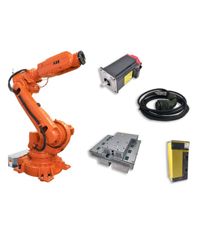

Choosing the correct replacement cable for an industrial robot is not always as simple as matching its length or connector appearance.
Two robot cables may look almost identical but have different electrical specifications, connector pin assignments, shielding structures, or signal configurations. Installing an incompatible cable can result in communication errors, encoder signal loss, power interruptions, unexpected robot alarms, or even damage to connected equipment.
This is particularly important when replacing cables for robot motors, encoders, Teach Pendants, external axes, and controller communication systems.
Before ordering a replacement robot cable, maintenance technicians and purchasing teams should verify three essential details:
Part Number: Identify the original cable specification and approved replacement.
Connector: Confirm the connector type, pin count, keying, and physical configuration.
Pinout: Verify the electrical connections and signal assignments.
This guide explains how to identify the correct industrial robot cable, what information to check before purchasing, and how to avoid common cable compatibility mistakes.
Industrial robot cables are designed for specific electrical and mechanical applications.
Depending on their function, they may transmit power, encoder feedback, control signals, communication data, or multiple signal types through a single cable assembly.
Using the wrong cable can create several problems:
Robot communication becomes intermittent.
Encoder feedback signals become unstable.
Servo motors fail to operate correctly.
Teach Pendants disconnect from the controller.
Robot alarms appear after cable replacement.
Electrical interference affects signal transmission.
Cable connectors cannot be installed correctly.
A cable that physically fits may still be electrically incompatible.
For example, an encoder cable and a motor power cable may have similar external dimensions, but their conductor arrangements, shielding requirements, and electrical functions are completely different.
Correct cable identification is therefore essential before placing a replacement order.
The most reliable starting point is the part number printed on the original cable label, identification tag, or manufacturer documentation.
A part number can help identify the cable's intended application, compatible equipment, and original specifications.
Check the following locations:
Cable identification labels.
Tags near the connector ends.
Cable assembly markings.
Robot maintenance manuals.
Electrical wiring diagrams.
Original spare parts lists.
Controller or robot equipment documentation.
Some industrial robot cables have identification markings printed directly on the cable jacket. Others use separate labels attached near the connector.
If the original label is damaged or missing, record any remaining markings and take clear photos of the cable assembly.
| Identification Detail | What to Verify |
|---|---|
| Original Part Number | Complete number, including suffixes |
| Manufacturer | Original cable manufacturer or supplier |
| Cable Type | Power, encoder, signal, data, or Teach Pendant |
| Cable Length | Original specified length |
| Cable Assembly | Complete assembly or individual cable |
| Revision | Applicable design or assembly revision |
| Replacement Number | Whether an approved successor exists |
Some manufacturers use similar part number structures for cables designed for different applications.
A small suffix difference may represent a different cable length, connector arrangement, conductor configuration, or hardware revision.
Do not assume that two cables are interchangeable simply because most of their part numbers are identical.
When sourcing a replacement, confirm whether the proposed part is:
An exact original replacement.
An officially superseded part number.
A verified compatible alternative.
A visually similar but unverified cable.
These categories should not be treated as equivalent.
If the original part number is unavailable, identifying the cable's application is the next step.
Industrial robots use several different cable types, each designed for a specific function.
| Robot Cable Type | Main Function | Common Identification Points |
|---|---|---|
| Robot Motor Power Cable | Supplies electrical power to servo motors | Power conductors, motor-side connectors |
| Encoder Cable | Transmits motor position and feedback signals | Multi-pin connectors, signal shielding |
| Teach Pendant Cable | Connects the operator pendant to the controller | Pendant-specific connectors and cable assembly |
| Robot Signal Cable | Transmits control and I/O signals | Signal conductors and terminal configurations |
| Data / Communication Cable | Transfers communication data | Communication interface and cable specifications |
| External Axis Cable | Connects additional axes and associated equipment | Axis-specific electrical configuration |
| Robot Harness Assembly | Combines multiple cable connections | Multiple connectors and integrated cable routing |
| Dress Pack Cable | Supports cable routing along robot arms | Flexible construction and application-specific routing |
The cable's function helps narrow down the replacement options, but it does not establish complete compatibility.
For example, knowing that a cable is an ABB encoder cable or a FANUC motor cable is not sufficient to select the correct replacement. The original part number, connector configuration, and electrical specifications must still be checked.
The connector is one of the most visible features of a robot cable, making it useful for initial identification.
However, connector appearance alone is not enough to confirm compatibility.
Two connectors may have similar housings but different internal pin arrangements or electrical specifications.

1. Connector Type
Identify whether the cable uses a circular connector, rectangular connector, multi-pin industrial connector, or another specialized interface.
2. Pin Count
Count the number of pins or contact positions.
Make sure to distinguish between the actual installed contacts and the total available positions.
3. Connector Gender
Check whether the connector has male pins or female sockets.
4. Keying and Orientation
Inspect the connector's keyways, alignment features, locking mechanism, and orientation.
These features prevent incorrect installation in compatible systems.
5. Connector Dimensions
Measure the connector housing and relevant mounting dimensions when necessary.
6. Connector Manufacturer and Model
Where available, record the connector manufacturer's identification and model number.
| Item | Identification Method |
|---|---|
| Connector Shape | Take a clear front and side photo |
| Pin Count | Count contacts and available positions |
| Male / Female | Check contact configuration |
| Keying | Inspect alignment slots and positioning |
| Locking Mechanism | Identify threaded, bayonet, or other locking types |
| Housing Dimensions | Measure the connector body |
| Part Marking | Record manufacturer and connector model |
Important: A connector that physically fits does not automatically mean the cable is electrically compatible. Always verify the pin assignment and electrical specifications before installation.
The pinout is one of the most important factors in robot cable identification.
A pinout describes how individual connector pins are assigned and connected within a cable assembly.

It determines which conductors carry power, ground, feedback signals, communication data, and other electrical functions.
Two cables can have identical connectors and pin counts but completely different pin assignments.
A typical cable pinout may include:
Connector pin number.
Signal name.
Wire or conductor identification.
Electrical function.
Ground or shield connection.
Corresponding pin at the opposite connector.
For example, a simplified connector mapping might look like this:
| Connector A | Connector B | Function |
|---|---|---|
| Pin 1 | Pin 1 | Signal A |
| Pin 2 | Pin 2 | Signal B |
| Pin 3 | Pin 3 | Signal C |
| Pin 4 | Shield / Ground | Shield connection |
This is an illustrative example only, not an actual industrial robot cable pinout.
Actual pin assignments vary by manufacturer, cable model, and application.
Consider two cables with identical connector housings and the same number of pins.
One may be designed for an encoder feedback circuit, while the other uses a different signal configuration.
If the replacement cable has incorrect pin assignments, possible consequences include:
Missing or incorrect feedback signals.
Communication failures.
Incorrect signal detection.
Servo or encoder alarms.
Electrical short circuits.
Damage to connected electronic components.
For this reason, pinout verification should be part of the replacement process whenever the cable is not an exact, verified part-number match.
Use the following process:
Obtain the original cable wiring diagram or manufacturer pinout documentation.
Identify both connector ends.
Confirm the connector orientation and pin numbering convention.
Compare the signal assignments at both ends.
Verify conductor continuity using an appropriate test method.
Check shielding and grounding arrangements.
Confirm the replacement cable against the original electrical specifications.
Do not assume that connector pin numbering is viewed from the same direction in every drawing. Manufacturer diagrams may show the mating face, wiring side, or another reference orientation.
For motor power and encoder circuits, use the relevant manufacturer documentation and qualified electrical testing procedures. Never apply power to an unidentified cable to determine its pinout.
Even when the part number and connector configuration appear correct, other cable specifications should be checked.
Industrial robot cables operate in demanding environments. Their mechanical and electrical properties are important for reliable operation.
The replacement cable should match the required installation length.
A cable that is too short may create excessive tension during robot movement. A cable that is unnecessarily long may create routing problems, interference, or additional mechanical stress.
For dress packs and moving robot applications, the specified cable routing and working length are particularly important.
Shielding helps protect electrical signals from electromagnetic interference.
Different applications may require different shielding structures, including individual pair shielding or overall cable shielding. This is particularly important for:
Do not assume that two cables with the same number of conductors have equivalent shielding performance.
Check the conductor count, conductor cross-section, insulation, and electrical ratings against the original requirements. These specifications affect current capacity, signal transmission, and overall compatibility.
Robot cables may experience continuous bending, twisting, vibration, and movement. A standard industrial cable is not necessarily suitable for installation on a moving robot axis. Check whether the replacement is designed for:
A cable with the correct connector and electrical configuration may still fail prematurely if its mechanical construction is unsuitable for the application.
Many cable replacement problems result from incomplete identification rather than a lack of available products.
The following mistakes should be avoided.
| Common Mistake | Why It Is a Problem | Correct Approach |
|---|---|---|
| Matching only the cable appearance | Similar cables may have different internal specifications | Verify part number and electrical configuration |
| Checking only the connector shape | Connector fit does not guarantee electrical compatibility | Confirm pinout and connector specifications |
| Ignoring part number suffixes | Suffixes may indicate different cable configurations | Compare the complete part number |
| Ignoring cable length | Incorrect length can affect installation and movement | Verify original length and routing |
| Using standard cable for robot movement | Mechanical construction may not support continuous flexing | Confirm robot-rated cable requirements |
| Ignoring shielding | Signal interference may cause communication or feedback problems | Match shielding specifications |
| Assuming all cables from one brand are interchangeable | Different robot models and generations use different assemblies | Verify the specific robot and controller application |
A reliable replacement decision should be based on complete identification, not a single matching feature.
If the original part number is unavailable or the cable has been damaged, providing detailed information to your supplier can help speed up identification.
Use the following checklist before requesting a quotation.
| Required Information | What to Provide |
|---|---|
| Robot Brand | ABB, FANUC, KUKA, Yaskawa, etc. |
| Robot Model | Exact robot model |
| Controller Model | Controller generation and model |
| Original Cable Part Number | Complete number, including suffix |
| Cable Application | Motor, encoder, signal, power, data, pendant, etc. |
| Connector A | Front-facing photo and pin count |
| Connector B | Front-facing photo and pin count |
| Cable Length | Original or required length |
| Pinout Diagram | If available |
| Cable Markings | Printed identification and manufacturer details |
| Quantity | Required replacement quantity |
You can still provide useful identification information.
Take clear photos of:
The entire cable assembly.
Both connector ends.
Connector front faces showing the pin arrangement.
Any remaining cable jacket markings.
The robot and controller identification labels.
If the cable is damaged, photograph the damaged section as well.
For more complex cable assemblies, a wiring diagram or original equipment documentation can provide additional information.
The supplier may need to compare the physical configuration with available technical documentation before confirming a replacement.
When the original robot cable is discontinued or difficult to source, a compatible alternative may be worth considering.
However, compatibility should be evaluated carefully.
An exact original replacement is generally the preferred option when the original part number and specifications are confirmed.
It reduces uncertainty about connector configuration, electrical characteristics, and intended application.
Some manufacturers replace older cable part numbers with updated versions.
In these cases, verify whether the new part number is an approved successor and whether any installation changes are required.
A compatible alternative may be suitable when the original part is unavailable.
However, the replacement should be checked against the original cable's:
Electrical specifications.
Connector and pinout configuration.
Cable length.
Shielding requirements.
Mechanical flexibility.
Environmental and installation requirements.
A cable should not be considered compatible based only on matching connectors or external dimensions.
For robot applications, incorrect electrical connections can create serious equipment risks. Alternative cables should only be used when their compatibility has been properly verified.
Finding the correct robot cable requires more than identifying its appearance.
Part number, connector configuration, pinout, electrical specifications, and mechanical requirements all contribute to successful replacement.
InRobots provides industrial robot spare parts sourcing for major manufacturers, including ABB, FANUC, KUKA, and Yaskawa.
Our robot cable product range covers different industrial robot applications, including:
Robot Motor Power Cables
Encoder Cables
Teach Pendant Cables
Robot Signal Cables
Data and Communication Cables
External Axis Cables
Robot Harness Assemblies
Other Robot Cable and Connectivity Components
Whether you need an exact replacement cable or help identifying a hard-to-find cable assembly, providing the original part number and connector photos is the best starting point.
Explore our Robot Cables & Connectivity collection to find relevant industrial robot cable solutions.
If you cannot identify the correct cable, contact InRobots with your robot model, controller information, cable markings, and connector photos.
Start by identifying the robot brand, robot model, controller model, cable application, connector types, and cable length. Clear photos of both connectors and any remaining cable markings can help with identification. A wiring diagram is useful when pinout verification is required.
Not necessarily. Two cables may have identical connector housings but different pin assignments, electrical ratings, shielding, or mechanical specifications. Verify the complete cable configuration before using a replacement.
Pinout determines how electrical signals are connected between the two ends of the cable. Incorrect pin assignments can cause communication errors, missing encoder feedback, electrical faults, or damage to connected components.
Use the manufacturer's wiring diagram or cable specification. Confirm connector orientation, pin numbering, signal assignments, and shielding connections. Continuity testing can help verify conductor connections when performed using appropriate procedures.
Yes, in some cases. However, the alternative must meet the original electrical, connector, shielding, length, and mechanical requirements. Similar appearance alone is not sufficient evidence of compatibility.
Yes. The cable must be suitable for the installation distance and routing requirements. Incorrect length may create excessive tension, poor routing, or additional mechanical stress during robot movement.
A motor power cable supplies electrical power to the servo motor, while an encoder cable transmits feedback signals used by the robot control system. They have different electrical functions and should not be treated as interchangeable.
Possible causes include incorrect cable pinout, damaged connectors, poor contact, incompatible shielding, or a defective replacement cable. Check the manufacturer's wiring diagram and verify the cable assembly before investigating other components.
Identifying the correct industrial robot cable requires more than matching its connector or external appearance.
The original part number, cable application, connector configuration, pinout, electrical specifications, and mechanical requirements must all be considered before ordering a replacement.
A systematic identification process helps maintenance teams avoid incompatible cables, reduce unnecessary troubleshooting, and minimize robot downtime.
When the original part number is unavailable, detailed connector photos, controller information, and wiring documentation can help narrow down suitable replacement options.
Need help identifying an industrial robot cable?
Send InRobots your original part number, robot model, controller details, and connector photos. Our team can help identify suitable robot cable and connectivity spare parts for your application.
Key components commonly involved in issues and replacements.
No related parts found. Please check available components in our catalog.


{"one"=>"Seleziona 2 o 3 articoli da confrontare", "other"=>"{{ count }} di 3 elementi selezionati"}
Seleziona il primo elemento da confrontare
Seleziona il secondo elemento da confrontare
Seleziona il terzo elemento da confrontare
Lascia un commento