

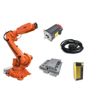

When a FANUC robot displays SRVO-214 – Fuse Blown (Servo Amplifier), the controller has detected a blown fuse in the servo amplifier.
The alarm indicates a hardware protection issue, but it does not automatically mean the servo amplifier is the only faulty component.
On many FANUC R-30iA and R-30iB systems, the first diagnostic step is to identify whether fuse FS2 or FS3 has blown. These fuses protect different circuits, so the accompanying alarms and troubleshooting procedures are different.
Replacing the servo amplifier without checking the connected circuits may leave the original fault unresolved.
This guide explains what FANUC SRVO-214 means, how to distinguish FS2 and FS3 failures, which components should be inspected, and when servo amplifier replacement may be necessary.
SRVO-214 – Fuse Blown (Servo Amplifier) indicates that a fuse inside the servo amplifier has blown.
On FANUC R-30iB controllers, the alarm is also described as:
SRVO-214 – 6ch amplifier fuse blown
The servo amplifier contains several protective fuses. On commonly used R-30iA and R-30iB configurations, FS2 and FS3 are associated with the SRVO-214 troubleshooting procedure.
Their functions are different:
| Fuse | Protected circuit | Main troubleshooting direction |
|---|---|---|
| FS2 | 24V output circuit for end-effector and related robot functions | Check +24VF ground faults and robot cabling |
| FS3 | 24V output circuit for the regenerative resistor | Check the regenerative resistor and related equipment |
FS1 has a different function. It supplies power to the amplifier control circuit. When FS1 fails, all servo amplifier LEDs may go out and an FSSB disconnection or initialization alarm may appear instead of the typical SRVO-214 symptoms.
The exact fuse arrangement depends on the amplifier and controller configuration. Always verify the applicable FANUC maintenance manual before diagnosing or replacing components.
The symptoms accompanying SRVO-214 can help identify which circuit requires inspection.
When FS2 blows, the following alarms may appear together:
SRVO-214 – Fuse Blown (Servo Amplifier)
SRVO-006 – Hand Broken
SRVO-005 – Robot Overtravel
These alarms can indicate a problem in the +24VF circuit used by the end effector or related robot connections.
Possible inspection points include:
End-effector 24V wiring
Robot connection cable
Internal robot cable
Robot-mounted equipment connected to the protected 24V circuit
Internal fan motor on applicable M-3iA configurations
The presence of SRVO-006 or SRVO-005 alongside SRVO-214 is useful diagnostic information. It should not be treated as proof that the hand or overtravel system itself is the root cause.
When FS3 blows, the typical accompanying alarms are:
SRVO-214 – Fuse Blown (Servo Amplifier)
SRVO-043 – DCAL
This combination directs attention toward the regenerative resistor circuit.
The regenerative resistor dissipates electrical energy generated during robot deceleration and other regenerative operating conditions.
A defective resistor or related wiring problem may cause the protected circuit to fail.
The cause depends on which fuse has blown.
A ground fault in the +24VF circuit used by the end effector is one of the main causes associated with FS2 failure.
Potential problem areas include:
Damaged end-effector wiring
Pinched or crushed cables
Insulation deterioration
Damaged connectors
Short circuits in connected equipment
A damaged cable may create an intermittent fault when the robot moves, making the problem difficult to identify through a visual inspection alone.
The robot connection cable carries electrical connections between the controller and the robot.
Cable damage, insulation failure, or an internal short circuit can affect the protected circuit and cause fuse failure.
Inspect the cable for:
Crushed or deformed sections
Damaged insulation
Connector contamination or damage
Signs of overheating
Evidence of repeated mechanical stress
Do not assume the cable is defective based on appearance alone. Electrical testing should be performed according to the applicable FANUC procedure.
The robot internal cable routes electrical connections through the robot structure.
Repeated movement, mechanical interference, or insulation deterioration can damage the wiring over time.
For FS2-related failures, the FANUC maintenance procedure specifically identifies the robot connection cable and internal robot cable as inspection points.
When SRVO-214 appears together with SRVO-043 DCAL, the regenerative resistor should be investigated.
Possible problems include:
Internal resistor damage
Short circuit in the resistor circuit
Damaged connecting wires
Defective connectors
Abnormal resistance values
The regenerative resistor should be checked against the specifications for the installed controller and amplifier.
Some FANUC configurations include additional axis equipment.
When FS3-related troubleshooting involves an additional axis amplifier, its wiring and associated components should also be checked.
This is particularly important when the installed system includes external axes or other optional motion equipment.
Do not apply an additional-axis troubleshooting procedure to a standard six-axis configuration without confirming that the option is installed.
The following approach helps maintenance teams identify the faulty circuit before replacing major components.
Before resetting the controller, record the complete alarm history.
Pay particular attention to the alarms appearing together with SRVO-214.
| Alarm combination | Main inspection direction |
|---|---|
| SRVO-214 + SRVO-006 + SRVO-005 | FS2 / +24VF / end-effector circuit |
| SRVO-214 + SRVO-043 | FS3 / regenerative resistor circuit |
| FSSB disconnection or initialization alarm with all amplifier LEDs off | Investigate FS1 and amplifier control power |
These combinations are diagnostic clues, not substitutes for confirming the actual blown fuse.
Confirm the following information:
FANUC controller model
Servo amplifier model
Robot model
Number of controlled axes
Whether additional axes are installed
Applicable maintenance manual revision
Locate the correct fuse identification diagram in the maintenance manual.
Do not assume every FANUC servo amplifier uses the same fuse arrangement.
If the symptoms point toward FS2:
Inspect the end-effector +24VF circuit for a ground fault.
Check the robot connection cable.
Inspect the robot internal cable.
On applicable M-3iA configurations, check the internal robot fan motor.
Identify and correct the actual fault before restoring the system.
A damaged cable or connected device should be repaired or replaced before the amplifier is returned to service.
If SRVO-043 DCAL appears together with SRVO-214:
Inspect the regenerative resistor.
Check the resistor and its connecting wires for damage.
Verify the electrical condition against the applicable specifications.
If an additional axis amplifier is installed, inspect its wiring and related equipment.
Correct the identified fault before restoring operation.
If the regenerative resistor is defective, replace it with the correct specification.
After the external circuits have been checked and the underlying cause has been corrected, evaluate the servo amplifier.
If the fuse has blown and the applicable FANUC manual specifies amplifier replacement, follow that procedure.
Do not repeatedly replace fuses or restart the controller without identifying the reason for the original failure.
After the repair:
Confirm that the original fault has been corrected.
Check the relevant wiring and connections.
Verify that the correct amplifier and replacement components are installed.
Restore power according to the controller maintenance procedure.
Check whether SRVO-214 or related alarms return.
Perform the required operational and safety checks before returning the robot to production.
This depends on the amplifier design and the applicable FANUC maintenance procedure.
FANUC maintenance manuals for several R-30iA and R-30iB configurations instruct technicians to eliminate the cause of the blown fuse and then follow the specified replacement procedure. They also list servo amplifier replacement as a subsequent action.
This does not mean that every SRVO-214 case can be repaired by installing a new fuse.
Before deciding what to replace, distinguish between the following situations:
| Situation | Recommended direction |
|---|---|
| FS2 blown, external +24VF ground fault found | Correct the ground fault and follow the manual's fuse/amplifier procedure |
| FS3 blown, regenerative resistor defective | Correct or replace the defective resistor and follow the manual's procedure |
| Robot cable or internal cable damaged | Repair or replace the affected cable and verify the amplifier |
| Fuse failure persists after the external cause is corrected | Evaluate or replace the servo amplifier as specified by FANUC |
| Amplifier has additional internal damage | Replace the complete amplifier with the correct compatible unit |
Important: Do not install a fuse with a higher rating, bypass a protective fuse, or repeatedly replace a fuse that blows again. These actions can damage the amplifier and create additional electrical hazards.
A common source of confusion is the difference between a servo amplifier and a power supply module.
They are related parts of the robot controller's electrical system, but they perform different functions.
| Component | Main function | Relevance to SRVO-214 |
|---|---|---|
| Servo Amplifier | Controls servo motor operation and provides power to the motor circuits | Directly associated with the SRVO-214 fuse |
| Power Supply Unit | Provides the electrical power required by the controller and drive system | Not automatically the faulty component when SRVO-214 appears |
| Regenerative Resistor | Dissipates regenerated electrical energy | Important inspection point for FS3-related faults |
| Robot Cable | Carries electrical connections between controller and robot | Important inspection point for FS2-related faults |
SRVO-214 specifically identifies a fuse failure in the servo amplifier. It should not automatically be diagnosed as a power supply unit failure.
When sourcing a replacement, identify the exact component from its nameplate and part number rather than relying only on the alarm description.
If the servo amplifier needs replacement, verify the following information before purchasing.
Identify the controller generation and configuration, such as:
FANUC R-30iA
FANUC R-30iB
FANUC R-30iB Mate
FANUC R-30iB Mate Plus
FANUC R-50iA
These controller families may use different amplifier designs and maintenance procedures.
Check the complete part number on the existing amplifier nameplate.
Do not select a replacement based only on the robot model or the SRVO-214 alarm.
Confirm whether the amplifier is intended for:
Standard six-axis robot operation
An additional-axis configuration
A specific controller or robot system
Compare the original unit and replacement for:
Electrical ratings
Connector arrangement
Mounting dimensions
Supported controller configuration
Applicable hardware revisions
A similar-looking amplifier is not necessarily interchangeable.
If you need a replacement FANUC servo amplifier or related power component, prepare the following information:
| Information | Why it matters |
|---|---|
| Controller model | Identifies the controller generation |
| Robot model | Helps confirm the system configuration |
| Servo amplifier part number | Supports exact component identification |
| Amplifier nameplate photo | Helps verify the complete part number |
| Alarm history | Shows whether SRVO-214 appeared with SRVO-006, SRVO-005, or SRVO-043 |
| Fuse identification | Helps distinguish FS2 and FS3 failures |
| Required quantity | Supports quotation preparation |
Providing clear nameplate photos and the complete part number can reduce the risk of selecting an incompatible replacement.
SRVO-214 means that a fuse in the FANUC servo amplifier has blown. On many R-30iA and R-30iB configurations, the troubleshooting procedure focuses on FS2 and FS3.
FS2 protects a 24V output circuit associated with the end effector and related robot functions. FS3 protects the 24V output circuit associated with the regenerative resistor. Their accompanying alarms and troubleshooting directions are different.
SRVO-043 is a DCAL alarm. When it appears with SRVO-214, the regenerative resistor circuit should be inspected because it is associated with the FS3 protection circuit.
Not necessarily. A ground fault, damaged robot cable, defective regenerative resistor, or related wiring problem may be responsible for the fuse failure. The original cause should be identified before replacing the amplifier.
Fuse replacement should only be performed by qualified personnel following the correct FANUC maintenance procedure. The cause of the failure must be identified and corrected first.
The servo amplifier can retain dangerous DC-link voltage after the controller is switched off. Before touching the amplifier, follow the manufacturer's discharge and voltage-verification procedure. Do not assume the circuit is safe simply because the power is off.
No. SRVO-214 concerns a fuse in the servo amplifier. SRVO-215 is a separate fuse-related alarm associated with the additional-axis amplifier on applicable FANUC systems. Always check the exact alarm description and controller manual.
If your FANUC robot displays SRVO-214, identifying the failed fuse circuit is the first step toward selecting the correct replacement.
InRobots supports sourcing industrial robot spare parts, including FANUC servo amplifiers and related components.
When requesting a quotation, provide:
Complete servo amplifier part number
FANUC controller and robot model
Nameplate photos
SRVO-214 alarm history and accompanying alarms
Required quantity
If the original amplifier part number is unavailable or difficult to identify, send us a photo of the nameplate for assistance.
45,000+ parts in stock · Fast worldwide shipping · Hard-to-find parts sourcing.
Key components commonly involved in issues and replacements.
No related parts found. Please check available components in our catalog.


{"one"=>"Select 2 or 3 items to compare", "other"=>"{{ count }} of 3 items selected"}
Leave a comment on this topic