

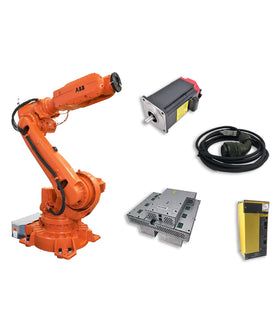

When a FANUC robot displays SRVO-059 Servo Amp Init Error, the controller has failed to initialize the servo amplifier.
This alarm can prevent the robot from completing its startup sequence and may leave the affected servo system unavailable.
Although the servo amplifier is the component named in the alarm, it is not necessarily the only possible source of the problem.
Depending on the controller generation, the cause may involve the optical fiber communication link, amplifier power supply, robot connection cable, internal Pulse Coder cable, servo amplifier, or another connected component.
Replacing the servo amplifier without checking these areas first may result in unnecessary repair costs.
This guide explains what FANUC SRVO-059 means, the components involved, and how to approach the diagnosis before deciding which replacement part is required.
SRVO-059 – Servo Amp Init Error
SRVO-059 indicates that the FANUC controller has failed to initialize the servo amplifier.
During startup, the controller must establish communication with the servo amplifier and confirm that the required hardware and power conditions are available.
If initialization fails, the controller generates SRVO-059.
On applicable R-30iB controllers, the alarm message may include:
Group (G): Identifies the robot or motion group.
Axis (A): Identifies the associated axis.
Additional diagnostic information, depending on the controller generation.
Record the complete alarm message rather than only the SRVO-059 code. This information helps identify the affected servo system.
A FANUC Servo Amplifier is part of the robot's motion control system.
It receives control information from the controller and drives the servo motors that move the robot axes.
Its main functions include:
Controlling servo motor operation.
Receiving motion commands from the controller.
Processing motor feedback.
Supporting controlled movement of individual robot axes.
Communicating with the controller through the servo system interface.
If the amplifier cannot initialize correctly, the controller may be unable to establish normal servo operation.
FANUC maintenance documentation identifies several areas that should be checked when SRVO-059 occurs.
The exact troubleshooting sequence depends on the controller generation and servo amplifier configuration.
The optical fiber cable connects the main board's axis control or servo card to the servo amplifier.
This communication link is essential for the controller to initialize and communicate with the amplifier.
Possible problems include:
Damaged optical fiber.
Loose or improperly seated connectors.
Contaminated connector ends.
A broken fiber connection.
Communication failure between the controller and amplifier.
What to check:
Inspect the optical fiber connection between the main board and the servo amplifier.
If the fiber cable is damaged or faulty, replace it with the correct compatible cable.
Do not bend the fiber cable beyond its specified radius or touch exposed optical connector ends unnecessarily.
The servo amplifier requires its specified DC power supply to operate correctly.
If the required power is unavailable, the amplifier may fail to initialize.
On applicable R-30iB Mate systems, FANUC maintenance documentation specifies checking the P5V and P3.3V indicators on the 6-axis servo amplifier.
If these indicators are not illuminated, the manual directs maintenance personnel to investigate the DC power supply and relevant connectors.
Possible areas to inspect include:
Power supply output.
Connector CP5 on the power supply unit.
Connector CXA2B on the 6-axis servo amplifier.
Power connections and related wiring.
The connector names and indicator arrangements vary by controller generation. Use the correct maintenance manual for the installed hardware.
A fault in the robot connection cable or internal robot wiring may interfere with servo system initialization.
For applicable R-30iB configurations, FANUC documentation identifies a possible ground fault involving:
Robot connection cable RP1.
Robot internal Pulse Coder cable.
Related robot feedback wiring.
A damaged cable or insulation failure may affect the electrical condition of the servo system.
What to check:
A qualified technician should inspect the relevant cables and connectors using the applicable FANUC diagnostic procedure.
Do not assume that the servo amplifier is defective before checking the cable-related conditions identified in the maintenance manual.
If the optical fiber communication, power supply, and relevant cable connections are confirmed normal, the servo amplifier itself may be defective.
Possible signs include:
Initialization failure that remains after the external connections are verified.
Abnormal amplifier power indicators.
A confirmed internal amplifier fault.
Recurring SRVO-059 after the applicable troubleshooting steps.
FANUC maintenance documentation lists servo amplifier replacement as a corrective action for applicable controller configurations.
However, the amplifier should be replaced only after the preceding checks have been completed.
Some FANUC robot systems include additional hardware such as a line tracking board.
For certain R-30iB controller maintenance procedures, replacement of the line tracking board is listed as a possible corrective action if installed.
This does not mean every SRVO-059 alarm involves a line tracking board.
Only investigate this component when the robot configuration includes it and the applicable diagnostic procedure identifies it as a possible source.
Some controller generations also include motor or Pulse Coder checks in the SRVO-059 troubleshooting sequence.
For example, the R-30iB Mate/Mate Plus maintenance procedure lists motor replacement after the servo amplifier and optional line tracking board checks.
A problem in the motor feedback system may therefore need investigation when the earlier diagnostic steps do not resolve the alarm.
Do not confuse this with SRVO-064 PHAL, which specifically identifies an abnormal Pulse Coder pulse phase.
The following sequence summarizes the diagnostic areas identified in FANUC maintenance documentation.
The exact procedure must be selected according to the controller model and installed amplifier configuration.
Open the alarm history and confirm:
SRVO-059 Servo Amp Init Error.
Group number.
Axis number, if displayed.
Any additional diagnostic information.
Other alarms appearing at the same time.
Also record whether the alarm occurs immediately after power-up or follows another servo-related fault.
This information helps identify the affected servo system and avoid investigating unrelated components.
Inspect the optical fiber cable between the main board's axis control or servo card and the servo amplifier.
Check for:
Damaged fiber cable.
Loose connectors.
Incorrect connection.
Visible damage to the optical connector.
Evidence of previous repair or improper routing.
If the fiber cable is confirmed faulty, replace it with the correct compatible part.
If the optical fiber cable is normal, investigate the robot connection cable and internal robot wiring.
On applicable R-30iB configurations, FANUC specifies a diagnostic procedure involving the CRF8 connector on the 6-axis servo amplifier.
This procedure requires the controller to be powered down before the connector is disconnected. The manual also warns that SRVO-068 may appear as a consequence of disconnecting this connector and should be interpreted accordingly.
If the alarm disappears under the prescribed diagnostic conditions, a ground fault in the robot connection cable or internal Pulse Coder cable may be involved.
This is a maintenance-level diagnostic procedure. It must only be performed by qualified personnel following the exact FANUC manual. Do not disconnect connectors or perform electrical tests on energized equipment.
On the applicable 6-axis servo amplifier, inspect the power indicators specified by the controller maintenance manual.
For certain R-30iB Mate configurations, these include:
P5V
P3.3V
If the indicators are not illuminated, investigate whether the required DC power is reaching the amplifier.
Check the relevant power supply connectors and wiring according to the installed controller configuration.
If the connectors are properly connected but the required power remains unavailable, the servo amplifier or its power supply path may require further diagnosis.
If the optical fiber connection, robot connection cable, and amplifier power supply have been checked, evaluate the servo amplifier itself.
Look for evidence of:
Internal amplifier failure.
Abnormal power indicators.
Physical damage.
Persistent initialization failure after the required external checks.
If the maintenance procedure confirms an amplifier fault, replace the correct servo amplifier assembly.
If the controller configuration includes a line tracking board or other connected servo hardware, follow the applicable maintenance procedure to determine whether it requires inspection.
Do not replace optional hardware simply because SRVO-059 appears.
After replacing a component or correcting a wiring problem:
Confirm that the correct replacement part has been installed.
Follow the applicable FANUC startup procedure.
Check whether SRVO-059 has cleared.
Review the alarm history for additional servo faults.
Verify normal servo operation before returning the robot to production.
If the alarm remains, continue with the controller-specific troubleshooting procedure rather than repeatedly resetting the controller.
The following table summarizes the relationship between the diagnostic result and the component to investigate.
| Diagnostic Finding | Component to Investigate | Possible Action |
|---|---|---|
| Optical communication is interrupted | Optical fiber cable | Inspect and replace if faulty |
| Robot connection cable has a ground fault | RP1 / applicable robot connection cable | Inspect and replace damaged cable |
| Internal feedback wiring has a ground fault | Pulse Coder cable | Inspect and replace damaged cable |
| Amplifier power indicators are not illuminated | DC power supply and related connectors | Check power supply and connections |
| External connections and power are normal, but initialization still fails | Servo amplifier | Replace if confirmed defective |
| Optional line tracking hardware is faulty | Line tracking board | Inspect and replace if applicable |
| Motor-related fault is confirmed during diagnosis | Servo motor assembly | Replace according to the applicable procedure |
This distinction is important because SRVO-059 is an initialization alarm, not proof that the servo amplifier itself has failed.
SRVO-059 belongs to the broader FANUC servo system alarm group.
However, other alarms identify different problems.
| Alarm Code | Alarm Description | Main Diagnostic Area |
|---|---|---|
| SRVO-055 | FSSB Communication Error 1 | Servo communication |
| SRVO-056 | FSSB Communication Error 2 | Servo communication |
| SRVO-057 | FSSB Disconnect | Servo communication connection |
| SRVO-058 | FSSB Initialization Error | FSSB initialization |
| SRVO-059 | Servo Amp Init Error | Servo amplifier initialization |
| SRVO-064 | PHAL | Pulse Coder phase error |
| SRVO-068 | DTERR | Pulse Coder serial data response |
| SRVO-069 | CRCERR | Pulse Coder serial communication data error |
| SRVO-070 | STBERR | Pulse Coder serial data status error |
The distinction matters when selecting the replacement component.
For example:
SRVO-058 focuses on FSSB initialization.
SRVO-059 identifies servo amplifier initialization failure.
SRVO-064 identifies an abnormal Pulse Coder phase.
SRVO-068, SRVO-069, and SRVO-070 identify different Pulse Coder communication conditions.
Some alarms may appear together. Review the complete alarm history before deciding which component to replace.
If the servo amplifier is confirmed defective, selecting the correct replacement is essential.
FANUC servo amplifiers are available in different hardware configurations, capacities, and revisions.
A visually similar amplifier may not be compatible with the original system.
Before sourcing a replacement, collect the following information.
Record the complete part number from the amplifier identification label.
Include:
Full model or part number.
Hardware revision.
Any suffix or configuration code.
Relevant identification markings.
Do not order based only on the general description "FANUC Servo Amplifier."
Identify the installed FANUC controller generation, such as:
R-30iA
R-30iA Mate
R-30iB
R-30iB Mate
R-30iB Plus
R-50iA
The controller model helps establish which amplifier configurations and diagnostic procedures apply.
Confirm whether the original unit is:
A 6-axis servo amplifier.
An auxiliary-axis servo amplifier.
Another amplifier configuration.
Also record the applicable model and hardware identification.
Provide the complete robot model and the axis or group identified in the alarm.
This helps verify the installed servo system and the required amplifier configuration.
If the original part number is unclear, provide clear photos of:
Amplifier front panel.
Identification label.
Connector arrangement.
Relevant indicator area.
Existing installation, where practical.
These details help prevent ordering an incompatible replacement.
The correct replacement depends on the confirmed diagnostic result.
| Replacement Component | When to Consider It |
|---|---|
| Optical fiber cable | Communication cable is confirmed damaged |
| Robot connection cable | RP1 or related cable is confirmed faulty |
| Internal robot cable | Pulse Coder or motor wiring is confirmed damaged |
| Servo amplifier | Amplifier initialization failure is traced to the amplifier |
| Line tracking board | A fault is confirmed and the board is installed |
| Servo motor | The applicable diagnostic procedure confirms a motor-related failure |
Do not replace the complete servo amplifier system based only on SRVO-059.
The correct approach is to identify whether the failure is caused by communication, power, cabling, the amplifier, or another connected component.
Servo amplifier troubleshooting involves electrical equipment and potentially hazardous stored energy.
Before performing maintenance:
Follow the FANUC controller maintenance manual.
Turn off and isolate the controller power as specified.
Observe the required waiting time before touching internal components.
Be aware that dangerous voltage may remain inside the servo amplifier after power-off.
Use appropriate ESD precautions when handling electronic components.
Have qualified maintenance personnel perform electrical measurements and connector inspections.
Do not disconnect or reconnect servo system wiring while energized.
The R-30iB Mate maintenance documentation specifically warns that voltage may remain in the servo amplifier after the controller is switched off.
Never bypass protective circuits or use an improvised electrical connection to force the robot to initialize.
SRVO-059 means Servo Amp Init Error. The FANUC controller has failed to initialize the servo amplifier.
No. The alarm may involve the optical fiber communication link, amplifier power supply, robot connection cable, internal Pulse Coder wiring, or the servo amplifier itself.
The exact diagnostic sequence depends on the controller generation.
Yes. FANUC maintenance documentation for applicable R-30iB configurations identifies possible ground faults in the robot connection cable or internal Pulse Coder cable as conditions to investigate.
Start by recording the complete alarm information and checking the optical fiber communication link between the main board and servo amplifier.
Then follow the controller-specific procedure to investigate the robot connection cable, amplifier power supply, and other components.
SRVO-058 identifies an FSSB initialization error, while SRVO-059 identifies a servo amplifier initialization error.
Although they involve related servo communication and hardware, they are different alarm conditions.
It is not recommended. If the actual problem is a damaged optical fiber cable, ground fault, or power supply issue, installing another amplifier may not resolve the alarm.
Not necessarily. Some FANUC controller maintenance procedures include motor replacement as a later diagnostic action, but the motor should only be replaced when the applicable procedure identifies it as faulty.
If your FANUC robot displays SRVO-059, identifying the cause of the initialization failure is the first step toward selecting the correct replacement component.
InRobots supports sourcing FANUC servo amplifiers, servo motors, robot connection cables, and other hard-to-find industrial robot spare parts.
To help identify the correct component, provide:
FANUC robot model.
Controller model.
Complete SRVO-059 alarm message.
Original servo amplifier part number.
Amplifier configuration.
Photos of the amplifier identification label and connectors.
Description of the troubleshooting already performed.
Required quantity.
You can also explore our FANUC robot spare parts and servo-related components for replacement options.
Key components commonly involved in issues and replacements.
No related parts found. Please check available components in our catalog.


{"one"=>"Selecione 2 ou 3 itens para comparar", "other"=>"{{ count }} de 3 itens selecionados"}
Selecione o primeiro item para comparar
Selecione o segundo item para comparar
Selecione o terceiro item para comparar
Deixe um comentário