
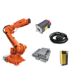


When a FANUC teach pendant stops working, the cause may be a power supply problem, damaged pendant cable, internal hardware failure, communication fault, or safety circuit issue.
The symptoms matter. A completely dead iPendant requires a different diagnostic approach from a pendant that powers on but displays a black screen, freezes during operation, or triggers an emergency stop alarm.
Before replacing the complete teach pendant, maintenance engineers should isolate the fault between the pendant, cable, controller connection, and safety circuit.
This guide covers common FANUC teach pendant problems, including power failures, display issues, unresponsive touchscreens, keypad problems, Deadman switch faults, and intermittent connections. It also explains how to identify the correct replacement parts for different FANUC controller configurations.
A FANUC teach pendant problem does not always mean the entire pendant has failed. Different symptoms can indicate different components or controller-side issues.
Use the following table to identify where to start.
| Symptom | Possible Causes | First Diagnostic Direction |
|---|---|---|
| Teach pendant will not power on | Controller power, fuse, cable, pendant hardware | Check controller status and the pendant power circuit |
| Black or blank screen | Power supply, LCD, internal hardware, startup issue | Determine whether the pendant completes its startup sequence |
| iPendant freezes or stops responding | Communication, software, internal hardware | Check whether the entire interface or only one function is affected |
| Touchscreen not responding | Touch panel or internal connection | Separate touch failure from LCD display failure |
| Some keys do not work | Membrane keypad or internal connection | Test individual keys and inspect the keypad |
| Deadman switch not working | Enabling device, cable, safety circuit | Check the active alarm and enabling-device status |
| Teach pendant E-Stop alarm | E-Stop button, wiring, cable, safety board | Identify the exact alarm and follow the controller-specific procedure |
| Pendant disconnects intermittently | Cable damage, connector, communication | Inspect cable routing and connector condition |
The first step is to identify the actual symptom rather than immediately replacing the pendant.
Before troubleshooting, place the robot in a safe condition and follow the site's lockout/tagout procedures where required.
Do not bypass emergency stop circuits, jumper safety signals, or perform live electrical checks unless you are qualified and authorized to do so.
If the FANUC teach pendant does not turn on, first confirm that the robot controller is powered and operating normally.
Check:
Is the controller circuit breaker on?
Is the controller displaying any power or hardware alarms?
Does the teach pendant show any LED indication or backlight?
Does the pendant display anything briefly during startup?
Did the problem occur after a power interruption or maintenance operation?
For applicable FANUC R-30iB Mate and R-30iB Mate Plus controllers, the maintenance manual includes a specific troubleshooting procedure for a teach pendant that cannot be powered on.
This procedure includes checking FUSE3 on the emergency stop board, the teach pendant cable, the teach pendant itself, and the related controller hardware.
Do not assume that every FANUC controller uses the same fuse arrangement or troubleshooting procedure. Always refer to the maintenance manual for the exact controller model.
The teach pendant cable carries the connections required for pendant operation. A damaged cable can cause power interruption, communication problems, or intermittent disconnection.
Inspect the following areas:
Cable sections with cuts, crushing, or visible deformation
Areas near the pendant handle and strain relief
Cable sections exposed to repeated bending or twisting
Connector housings and locking mechanisms
Signs of oil, moisture, or contamination
Pay particular attention to intermittent symptoms.
For example:
The pendant disconnects unexpectedly.
The display goes off and comes back.
The pendant restarts during operation.
Communication becomes unstable after cable movement.
These symptoms may indicate internal conductor damage or a connector problem.
However, moving the cable should not be used as a substitute for proper electrical testing. Do not flex or manipulate an energized cable in an unsafe manner.
For more detailed diagnosis, see our guide:
FANUC Teach Pendant Cable Failure: Symptoms, Diagnosis & Replacement Guide
A faulty connection between the teach pendant and controller can cause intermittent operation or communication loss.
Check:
Whether the connector is fully seated and secured
Whether connector pins are bent or damaged
Whether the connector housing is cracked
Whether there are signs of contamination or corrosion
Whether the cable is under excessive tension
Any connector inspection or electrical measurement should follow the applicable controller maintenance procedure.
If the connector is damaged, identify the correct replacement connector or cable assembly before ordering.
The FANUC teach pendant includes safety-related controls that affect robot operation.
Two important components are:
Emergency Stop Button
The E-Stop button must be in the released position before the robot can operate normally.
If the pendant displays an E-Stop alarm even when the button appears released, the problem may involve the switch, wiring, pendant cable, or controller-side safety circuit.
Deadman / Enabling Device
The Deadman switch is used to enable robot operation in applicable teach modes.
Check:
Whether the switch moves normally
Whether it returns properly when released
Whether the switch feels mechanically damaged
Whether the controller reports an enabling-device alarm
Do not bypass the enabling device or emergency stop circuit to restore operation.
If a safety-related fault remains, follow the controller-specific troubleshooting procedure and have the circuit checked by qualified personnel.
Once the initial checks are complete, determine which part of the system is responsible.
Where approved replacement components and test procedures are available, a qualified technician can use controlled substitution to isolate the fault.
| Test Result | Possible Conclusion |
|---|---|
| A verified compatible replacement cable restores operation | Original cable or its connector may be faulty |
| A verified compatible replacement pendant works | Original pendant assembly may be faulty |
| The same problem remains with a known-good pendant and cable | Investigate controller-side power, connection, or safety circuitry |
| Only the display or touch function fails | Investigate the relevant display or touch components |
A replacement pendant or cable must be verified for the specific controller and configuration. Similar appearance does not guarantee compatibility.
When a FANUC teach pendant stops responding or cannot enable robot operation, the alarm displayed on the controller is an important diagnostic clue.
The following examples are relevant to specific FANUC controller generations. Always confirm the alarm description and troubleshooting procedure against the maintenance manual for your controller.
What it indicates:
The emergency stop button on the teach pendant is pressed.
What to check:
Confirm whether the pendant E-Stop button is physically pressed.
Release the button if it has been activated.
If the alarm remains, inspect the E-Stop switch and related wiring according to the controller maintenance procedure.
Possible components involved:
Teach pendant E-Stop button
Teach pendant assembly
Related wiring and safety circuit components
Do not assume that the button itself is defective simply because the alarm remains active.
What it indicates:
The Deadman switch is released while the teach pendant is enabled.
This message does not automatically mean the switch has failed. It can be a normal status condition when the enabling device is not being pressed.
What to check:
Confirm the teach pendant is in the correct operating mode.
Check whether the enabling device is being operated correctly.
Inspect the switch for mechanical damage or abnormal movement.
If the alarm behavior is inconsistent, follow the relevant enabling-device diagnostic procedure.
Possible components involved:
Deadman / enabling device
Teach pendant internal wiring
Teach pendant assembly
What it indicates:
On applicable FANUC R-30iB Mate and R-30iB Mate Plus systems, this alarm relates to abnormal behavior of the enabling-device and emergency-stop signal circuit.
The controller maintenance manual identifies several possible components involved.
What to check:
Inspect the Deadman switch and its mechanical operation.
Check the teach pendant cable and related internal wiring.
Inspect the E-Stop board and relevant controller connections.
Follow the controller-specific diagnostic procedure to isolate the affected component.
Possible components involved:
Teach pendant
Teach pendant cable
E-Stop board
Servo amplifier
Controller internal cables
Main board
Do not replace the Deadman switch or complete pendant without confirming the fault location.
What it indicates:
On applicable FANUC controller configurations, SRVO-213 indicates that FUSE2 on the E-Stop board has blown or that the required external 24 V supply is not present.
What to check:
Verify the external 24 V supply according to the controller wiring diagram.
Check the relevant voltage terminals specified in the maintenance manual.
Inspect the external emergency-stop circuit for short circuits or grounding faults.
Check the related cable and E-Stop board.
Possible components involved:
Teach pendant cable
Teach pendant
E-Stop board
External emergency-stop power circuit
The alarm should not be treated as proof that the teach pendant itself has failed.
Important: Alarm definitions and corrective actions can vary by controller series and software configuration. These examples are not a substitute for the applicable FANUC maintenance manual.
Not all FANUC teach pendant display problems have the same cause.
A black screen, a frozen interface, and an unresponsive touchscreen should be investigated separately.
If the iPendant screen remains black, determine whether the entire pendant has lost power or whether the display itself has failed.
Check:
Whether the pendant shows any backlight.
Whether the controller is operating normally.
Whether the pendant completes its startup process.
Whether the problem appeared after a power interruption.
Whether the relevant controller alarms indicate a power or communication issue.
A completely dead pendant and a powered pendant with no visible image require different diagnostic procedures.
For an R-30iB Mate or Mate Plus controller, refer to the controller maintenance manual's procedure for a teach pendant that cannot be powered on or does not progress beyond the initial screen.
If the screen turns on but the interface freezes, investigate whether the problem affects the entire pendant or only a particular function.
Possible areas to investigate include:
Communication between the pendant and controller
Pendant internal hardware
Startup or application-related issues
Controller hardware or system status
Record the displayed alarms and the circumstances under which the problem occurs before attempting software recovery or replacement.
Avoid reloading software without confirming that the problem is actually software-related.
A visible image does not necessarily mean the touch function is working.
Likewise, a failed display does not automatically mean the touchscreen is defective.
| Symptom | Component to Investigate |
|---|---|
| Screen completely dark | Power circuit or LCD assembly |
| Backlight on but no visible image | Display assembly or related electronics |
| Image visible but touch does not respond | Touch screen or touch interface |
| Display works but some buttons fail | Membrane keypad |
| Screen flickers or loses display intermittently | Power connection, internal wiring, cable, or display assembly |
Before ordering replacement parts, identify the exact iPendant model and the component configuration.
The teach pendant cable is an important part of the connection between the operator interface and robot controller.
Cable damage can affect power, communication, and safety-related signals.
Look for:
Intermittent pendant disconnection
Random display interruption
Pendant restarting unexpectedly
Communication-related alarms
Visible cable damage
Damaged connector housings
Repeated problems after cable routing or maintenance work
Cable replacement may be necessary when:
The cable has visible physical damage.
Electrical testing identifies an open or damaged conductor.
The connector is damaged beyond repair.
A verified compatible replacement cable resolves the problem.
Do not replace a cable based only on an unrelated alarm code. Confirm the fault using the appropriate wiring diagram and diagnostic procedure.
Before ordering a replacement cable, verify:
Original cable part number
Teach pendant model
Controller series
Connector type and configuration
Cable length and routing requirements
A cable designed for another FANUC controller or pendant configuration may not be interchangeable.
See available Teach Pendant Cable Replacement Parts.
If troubleshooting confirms that the pendant assembly or one of its internal components has failed, the next step is to identify the correct replacement.
FANUC has used different teach pendant designs and part-number configurations across controller generations.
A replacement should not be selected based on brand name or appearance alone.
Locate the identification label on the pendant and record the complete part number.
Pay attention to:
A05B part number
Full suffix and revision
Connector configuration
Hardware version, where applicable
Small differences in part numbers can indicate different configurations.
Identify the robot controller before selecting a replacement.
Examples include:
R-J3 / R-J3iB
R-30iA
R-30iB
R-30iB Plus
These are controller families, not a universal compatibility list. The exact pendant and cable compatibility must be checked against the applicable hardware and configuration documentation.
If the original problem involves communication or intermittent disconnection, verify the cable separately from the pendant.
A compatible pendant with an incompatible cable will not provide a reliable replacement solution.
Depending on the confirmed failure, there may be no need to replace the entire teach pendant.
For example:
Display failure may require an LCD replacement.
Touch input failure may require a touch panel.
Keypad failure may require a membrane keypad.
Cable damage may require a replacement cable.
Housing damage may require a replacement cover or housing component.
Multiple internal failures may justify replacing the complete pendant.
The correct solution depends on the confirmed fault and the availability of compatible parts.
InRobots provides FANUC teach pendant replacement units and repair components for maintenance teams, robot service companies, and system integrators.
Depending on the original pendant model and confirmed fault, the required part may include:
For a failed pendant assembly that cannot be economically repaired, a compatible replacement iPendant may be the appropriate solution.
Browse FANUC Teach Pendant and iPendant Units
For cable-related power, communication, or connection problems, identify the original cable part number and connector configuration before ordering.
Browse Teach Pendant Cable Parts
If the display assembly is confirmed faulty while other pendant functions remain operational, an LCD replacement may be an option.
For a visible display with unresponsive or inaccurate touch input, investigate the touch panel separately from the LCD.
If individual keys fail or the keypad membrane is worn or damaged, a compatible membrane replacement may restore the affected input functions.
Other repair components may include buttons, switches, housings, and related internal components.
Browse FANUC iPendant Repair Parts
Component availability and compatibility depend on the exact pendant model.
A FANUC teach pendant that will not turn on may have a power supply issue, blown fuse, damaged pendant cable, internal pendant failure, or controller-side fault.
For applicable R-30iB Mate and Mate Plus systems, the maintenance procedure includes checking FUSE3 on the E-Stop board, the pendant cable, and the pendant itself.
A black screen may result from loss of pendant power, a display problem, internal hardware failure, or a startup issue.
First determine whether the pendant is completely dead or whether it powers on without displaying an image. These conditions require different diagnostic checks.
Yes. A damaged conductor, poor connector contact, or cable failure can interrupt communication between the teach pendant and controller.
However, communication alarms can also have other causes. Inspect the cable and verify the controller-side connection before deciding on a replacement.
SRVO-002 indicates a teach pendant E-Stop condition on applicable FANUC controllers.
Check whether the pendant emergency stop button is pressed. If it is released but the alarm remains, investigate the switch and associated safety circuit according to the controller maintenance manual.
The LCD displays the image, while the touch panel detects operator input.
If the image is visible but touch input does not work, the touch panel or its related interface should be investigated separately.
If the display is completely dark, the issue may involve the LCD assembly, power circuit, or other pendant hardware.
Possibly, but compatibility must be confirmed.
The replacement pendant, cable, connector configuration, and controller must all be compatible. Do not assume that a pendant will work with an existing cable simply because the connectors look similar.
Start with the original A05B part number, controller series, robot model, and connector photographs.
Providing these details makes it easier to identify the correct pendant, cable, or individual repair component.
Not every FANUC teach pendant failure requires a complete replacement.
Use the confirmed fault to determine the next step:
Cable damage: Replace the verified compatible cable.
LCD failure: Investigate the display assembly.
Touchscreen failure: Check the touch panel separately.
Keypad failure: Investigate the membrane keypad.
E-Stop or Deadman fault: Diagnose the complete safety-related circuit.
Multiple internal failures: Consider a compatible replacement pendant.
Controller-side fault: Investigate the relevant controller power, wiring, and safety components.
If the fault involves the E-Stop circuit, enabling device, or controller safety hardware, have the system inspected by qualified personnel before returning the robot to operation.
Not sure whether you need a complete iPendant, a replacement cable, an LCD display, or an individual repair component?
Send InRobots the following information:
Original FANUC part number
Robot and controller model
Photos of the pendant nameplate
Photos of the cable connector
Description of the fault or displayed alarm
Required quantity and delivery destination
Our team can help check the matching replacement or repair part for your FANUC system.
You can also browse our FANUC Teach Pendant and iPendant Parts for complete units and component-level repair options.
Explore the Full Guide: Industrial Robot Spare Parts → Industrial Robot Teach Pendant Center
Explore the complete guide for troubleshooting, repair strategies, and component replacement across industrial robot systems.
Key components commonly involved in teach pendants issues and replacements.


{"one"=>"Seleccione 2 o 3 artículos para comparar", "other"=>"{{ count }} de 3 artículos seleccionados"}
Seleccione el primer artículo para comparar
Seleccione el segundo artículo para comparar
Seleccione el tercer elemento para comparar
Dejar un comentario